 ISO 9001:2015 மற்றும் ISO 14001:2015 சான்றளிக்கப்பட்டது
 ISO 9001:2015 மற்றும் ISO 14001:2015 சான்றளிக்கப்பட்டது


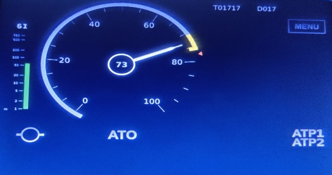
CMRL uses a Siemens-based Signalling and Train Control System for the Phase 1 project. It is based on Distance-to-Go technology with a Grade of Automation-2. Signaling sub-systems broadly comprise Computer Interlocking (CBI), Automatic Train Supervision (ATS), Automatic Train Protection (ATP) & Automatic Train Operation (ATO), with the end result being promoting safety, enhancing line capacity, and improving flexibility in the operation of Trains. The entire Signalling system is installed in a distributed architecture arrangement. The Central Train Supervision system is located in OCC and interfaced with other subsystems over a fiber backbone network.
ATO mode of train operation
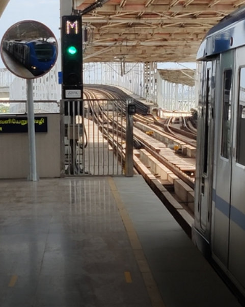
A train given clearance for departure in front of a Signal at Alandur station
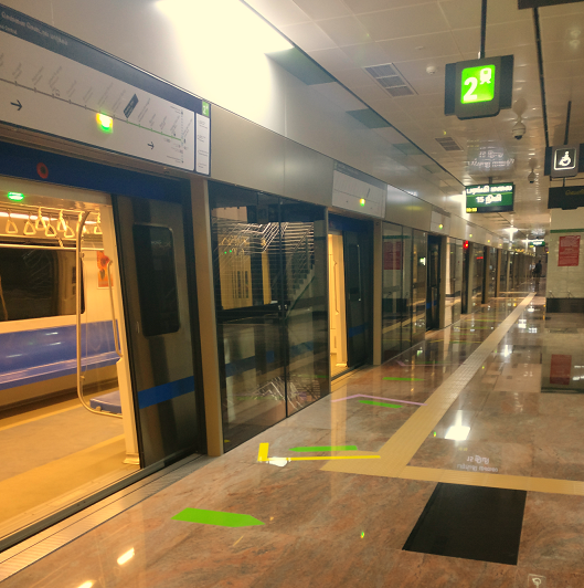
All 22 underground stations (48 platforms) of CMRL are equipped with Full Height Platform Screen Doors. The PSD system is installed between the track and passenger platform. They prevent unauthorized passenger access from the station track to the track and act as a partition to reduce the loss of conditioned air from the platform to the track area.
A typical PSD installation in
Telecommunication systems in Chennai metro rail covers locations like Operation control centre, Stations, Rolling Stock and Maintenance Depots. It is essential to have reliable link between various locations, moving trains and staff in various locations.
The Telecommunication systems provides all necessary communication channels / links for carrying Voice, Data and Video Signals for Control, Operations and Maintenance.
General Description of Vital Telecommunication Equipment in CMRL:
CBN Network provides a common Fibre Optic Cable based Transmission Backbone for all the Telecommunication Sub-systems and provides sufficient Transmission Bandwidth to interlink all Stations, OCC, DCC, RSS, Depot, Viaduct, Tunnel and Other Location’s needs of the Corridors as well as for future system expansion. Backbone systems are mainly to carry all systems Traffic (Voice, Data and Video).
TETRA is the acronym for Terrestrial Trunked Radio, which is an Open Standard for Digital Trunked Radio. The system is digital, wherein the speech is coded and passed through the system as digital data. The system supports both speech and data transmissions.
TETRA Radio System provides the voice and data communication for train, operations, maintenance and emergency communication needs of Operations Control Centre (OCC), Depot Control Centre (DCC), Receiver Sub-station (RSS), Depot, Station and Other Locations.
Instant communication is enabled using TETRA between Traffic Controller, Chief Controller, Other designated controllers in OCC, SCR, DCC and Train Driver, operations staff, maintenance staff & Security staff working at stations.
TETRA Coverage is provided inside and around the station building and along the viaduct. Leaky Coaxial Cables are installed for indoor/tunnel coverage.
The telephone system is provided with circuit based PBX comprising of digital and analog terminals implemented at Operations Control Centre (OCC), Depot Control Centre (DCC), and stations for voice communications. The Operational Telephone System shall be used solely to support railway operational processes involving train movements and activities related to those operations.
A modern, highly, reliable, expandable and high quality IP based PBX, office telephone system is provided to serve the stations of corridor-1 and corridor-2 for routine telephone communications between the CMRL locations and to locations external to the CMRL. The public switched Telephone Network is available to telephone extension users of the PBX System for External Calls through PRI Lines.
Passenger Emergency Telephone are available at each platform for passengers to contact Station Controller in case of any emergencies.
The Public Address / Voice Alarm (PA/VA) System is provided in the Operations Control Centre (OCC), stations and depot to support the broadcast of live voice announcements, pre-recorded messages, fire alarm messages to individual zones or combination of zones in each station.
PA/VA Systems at Station: In the station, the PA/VA System provides the station controllers at each Station Control Room (SCR) with the ability to address individual platform, concourse, non-public area or the entire station. Each station is partitioned into different zones of PA coverage.
Platform Announcement Point (PAP): A paging console is provided at the station platform to enable CMRL staff to make speech broadcast over the PA Zone relevant to that platform.
In the STAION Control Room a Standby Control Panel (SBCP) is available for the staff to perform announcement.
Audio-Frequency Induction Loop System (AFILS) is provided in each station. It enables all PA/VA broadcasts to be heard by those equipped with hearing aids enabled with T Coiled mode. It is provided in the designated area at station concourse ticketing area and platforms.
PIDS system is provided to present relevant information on train time and train destinations and also to facilitate the timely dissemination, current, real time and up-to-date travel information to the passengers through display units.
The following messages are displayed in the Stations at Passenger Ticket area and Platform.
CCTV surveillance system is provided for security and personnel surveillance throughout stations, Depot, OCC, electrical sub-stations
CCTV system is based on open standard integrated system with network centric functional and management architecture. Digital Video Recorder (DVR)/ Storage servers are provided in each location for recording the video captured by each camera for 30 days.
Fixed and PTZ cameras are installed in various locations of the station, admin building and depot. Playback Workstation is installed within the Recording Room with the capability for retrieval, viewing, storage, archiving of CCTV recordings throughout the OCC, DCC, RSS, Depot, Tunnel Cross Passage, Portal, Stations and Other Locations.
The Security Controller will be able to monitor and display live CCTV images from all the stations, line-side locations, the OCC Building and the Depot.
The station controller from Station Control Room (SCR) can select any camera within the station premises for live monitoring as well as playback of recorded video.
கடைசியாக புதுப்பிக்கப்பட்டது : August 3, 2024